Cable Tray Clearances

The Cable Tray Clearances plugin automates the creation and management of clearance zones around cable trays in Revit MEP projects. It enables you to apply customizable left, right, and top clearance values to selected cable trays, automatically placing clearance family instances at the correct locations and orientations. The plugin supports both bulk operations across all cable trays and selective processing for individual elements, ensuring compliance with electrical code regulations and design standards.
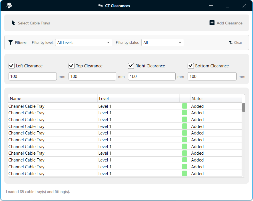
Figure 1.1: Cable Tray Clearances plugin interface overview
Features:
-
Select Cable Trays
- Choose between selecting individual cable trays or processing all cable trays in the project. Use the "Select Cable Trays" button to manually pick specific cable tray elements. The selection filter ensures only cable tray elements can be selected.
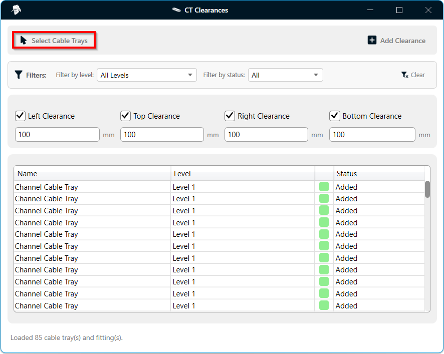
Figure 3.1: Selecting cable trays or running on all cable trays
-
Filters (Level & Status)
-
Filter cable trays directly within the interface to control which elements are displayed in the datagrid and which elements will receive clearances when using the Add Clearance button.
- Filter by Level
- Filter by Status (Added / Not Added / All)
-
Filter by Level: Select a specific building level from the dropdown to display only cable trays located on that level. This allows you to focus on managing clearances for a particular floor and simplifies navigation in large multi-level Revit projects.
-
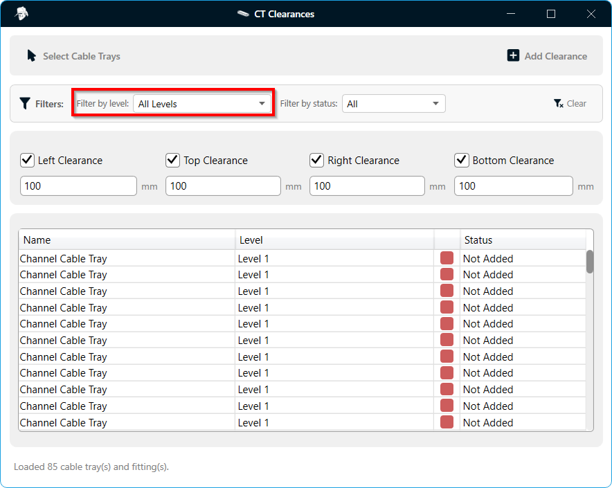
Figure 5.1: Filtering cable trays by building level
- Filter by Status: Filter cable trays based on their clearance status to quickly identify which cable trays already have clearance families added and which still require processing.
- 🟢 Green indicators represent cable trays with clearances already added.
- 🔴 Red indicators represent cable trays without clearances.
This visual filtering helps prioritize clearance placement and quality checking across the project.
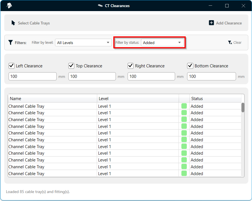
Figure 5.2: Filtering cable trays by clearance status (Added / Not Added)
-
Double-Click Isolation (3D Section Box)
- Double-click on the cable tray name in the datagrid to:
- Automatically isolate the cable tray in a 3D view.
- Apply a temporary section box around the selected element.
- This allows quick inspection and validation of clearance placement without manual navigation.
- Double-click on the cable tray name in the datagrid to:
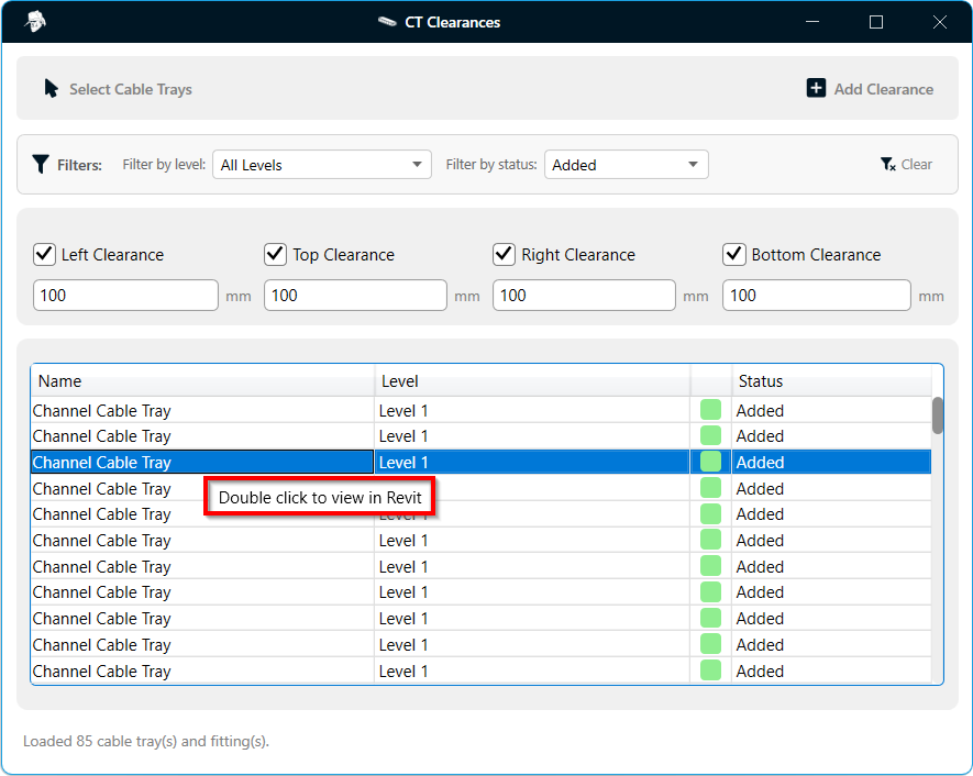
Figure 5.2: Double click on carble tray name to isolate in 3D.
- The image below shows an isolated cable tray where you can inspect and validate clearance placement in the 3D view.
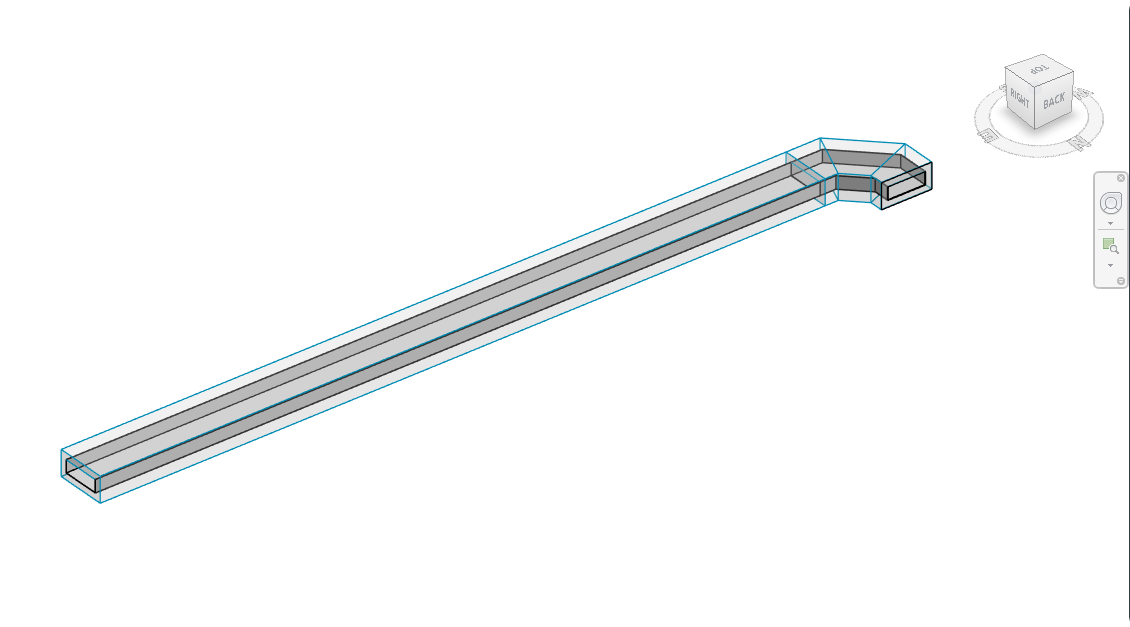
Figure 5.3: Isolated cable tray view where you can inspect and validate clearance placement in 3D.
-
Automatic Unit Detection & Display
- The plugin automatically detects the active unit system used in the current Revit project.
- Clearance input fields dynamically update to display the correct unit label based on project settings.
- Examples:
- Metric projects display (mm)
- Imperial projects display (ft)
- Other supported units reflect the project configuration
- Unit labels update automatically when project units change.
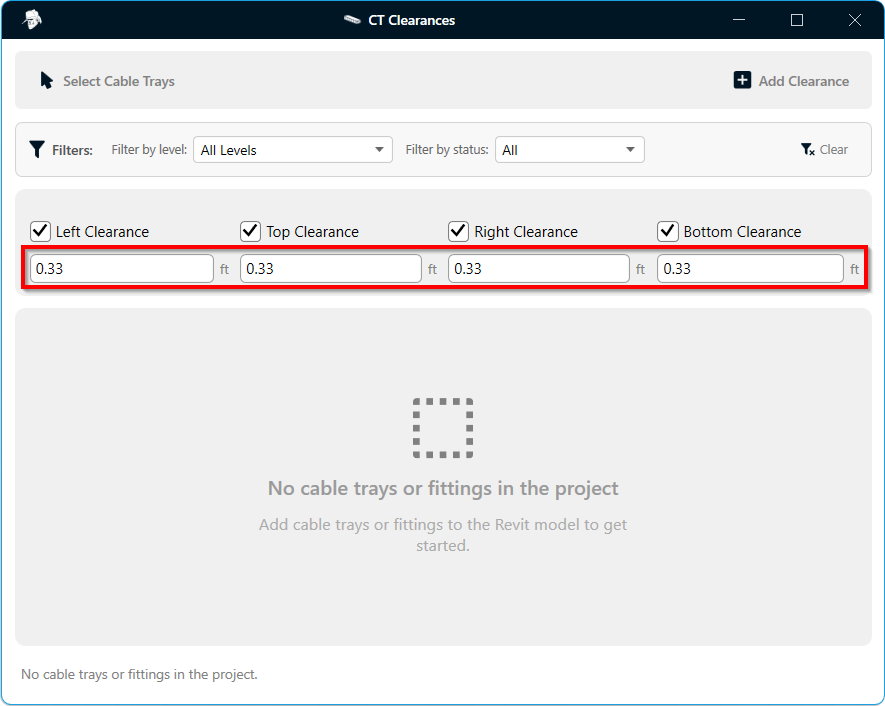
Figure 5.4: Clearance input fields automatically updating based on project units
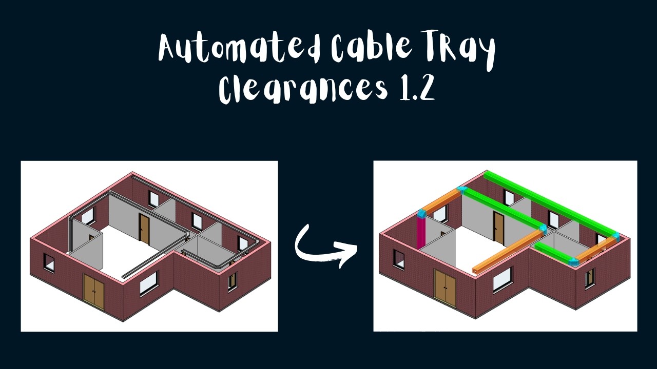
Video Demonstration
Watch the video below to see how the Cable Tray Clearances plugin works:
Download Plugin
Anyone can download the plugin and use it for 30 days. After that, you need to be a YouTube member to continue using the plugins.
- v1.0.4Latest18 Nov 2026 · 29.7 MB · Adds Wall Rebar.
- v1.0.34 Nov 2026 · 29.0 MB · Adds Foundation Rebar.
- v1.0.220 Sep 2026 · 13.7 MB · First public release.